


7 Critical Errors Your LED Display is Telling You: A 2026 Modified Sine Wave Troubleshooting Manual
- What is a modified sine wave inverter with an LED display?
- Key Takeaways: Quick Troubleshooting Summary
- Error 1: Low Battery Voltage Alarm (Red LED & Beeping)
- Error 2: Over-Voltage Protection Activation
- Error 3: Overload Fault (Load Exceeds Capacity)
- Error 4: Over-Temperature and Thermal Shutdown
- Error 5: Output Short Circuit Detection
- Error 6: Back EMF Feedback (The Modified Wave Hazard)
- Error 7: Battery Reverse Polarity Damage
- Expert Tips: Common Mistakes When Reading Inverter Displays
- Gap Analysis: What’s New in 2026 Inverter Diagnostics?
- Conclusion
- Why is the red fault light on my modified sine wave inverter?
- How do I reset a modified sine wave inverter after an error?
- Can a modified sine wave inverter run LED lights safely?
- What does a continuous beeping sound mean on my inverter?
- Why does my inverter display show a lower voltage than my battery?
- Are error codes the same for modified and pure sine wave inverters?
- How do I fix an overload error on my LED display?
- What is the standard operating temperature for a modified sine wave inverter?
Effective modified sine wave inverter troubleshooting begins with understanding the specific alerts flashing on your device's screen. If you are struggling with unexpected shutdowns, continuous beeping, or mysterious red lights, mastering your system's diagnostics is the key to preventing catastrophic electrical failure. This comprehensive guide will walk you through the most common 2026 inverter LED fault codes and how to resolve them safely.
What is a modified sine wave inverter with an LED display?
A modified sine wave inverter with an LED display is an electrical device that converts direct current (DC) into a stepped, blocky alternating current (AC). The integrated LED interface provides real-time monitoring of input/output voltage, load capacity, and operational status.
The visual display uses specific indicator lights and digital error codes to instantly alert users to critical system faults, battery drain, or load capacity issues. By converting power in a blocky, stair-step waveform, these budget-friendly devices efficiently power basic electronics and resistive loads. However, their simplistic waveform requires careful monitoring of the inverter LED fault codes to ensure you are not damaging sensitive equipment or overloading the internal circuitry.
Key Takeaways: Quick Troubleshooting Summary
Troubleshooting your inverter requires strict adherence to safety protocols to prevent shock hazards and hardware damage. Understanding these foundational steps ensures a secure diagnostic process.
- Disconnect Power First: Always disconnect your appliances before attempting to clear an inverter error code to protect both the load and the inverter's sensitive internal components.
- Decode the Lights: A solid red LED generally indicates a critical fault requiring an immediate shutdown, while flashing lights often signify pre-alarms like low battery voltage.
- Stay Updated: Understanding your specific model's 2026 updated diagnostic codes can save you from catastrophic system failure and costly replacements.
- Identify Load Types: Most errors on a modified sine wave inverter stem from connecting incompatible inductive loads or improper battery sizing.
Error 1: Low Battery Voltage Alarm (Red LED & Beeping)
The low battery voltage alarm occurs when the DC input drops below the safe operating threshold, typically triggering a flashing red LED and a continuous beep. This alert prevents the battery bank from suffering irreversible deep discharge damage.
When the input voltage falls (usually around 10.5V for a standard 12V system), the inverter's internal low-voltage disconnect (LVD) warns the user before automatically shutting down. This safety mechanism is crucial for preserving the lifespan of both traditional lead-acid and modern lithium iron phosphate batteries. Voltage drop can happen naturally as the battery drains, but it can also be artificially triggered by using DC cables that are too thin or too long to carry the required current.
Troubleshooting Steps:
- Disconnect the Load: Unplug all connected appliances immediately to stop the power draw.
- Recharge the System: Connect your battery bank to a charger or solar array to restore adequate resting voltage.
- Inspect Connections: Check for corroded terminals or loose cables, which cause resistance and trigger an artificial voltage drop.
Error 2: Over-Voltage Protection Activation
Over-voltage protection activates when the inverter receives a DC input exceeding its maximum safe limit, resulting in an "OVP" digital code or a high-voltage fault light. This safeguards the inverter's internal capacitors and circuitry from blowing out.
This error is frequently encountered when reading solar inverter display panels during peak sunlight or when a vehicle's alternator regulator malfunctions. If the voltage spikes above 15V on a standard 12V inverter, the system immediately cuts the output power. Cold weather can also cause solar charge controllers to push higher voltages than normal to compensate for temperature, accidentally tripping the inverter's safety thresholds.
Troubleshooting Steps:
- Isolate the Power Source: Disconnect the solar panels or turn off the vehicle's engine to halt the incoming power surge.
- Verify Controller Settings: Ensure your solar charge controller is properly calibrated for your specific battery chemistry.
- Test the Alternator: Use a digital multimeter to verify that the vehicle alternator regulator is functioning correctly and not overcharging the battery bank.
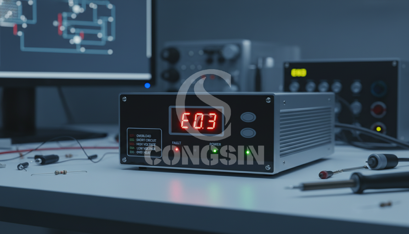
Error 3: Overload Fault (Load Exceeds Capacity)
An overload fault occurs when connected devices draw more continuous or surge wattage than the inverter is rated for, causing a sudden shutdown accompanied by an "OL" display code or solid red LED. This is the primary focus of overload protection inverter 2026 standards.
Inverters possess a specific continuous rating and a peak surge rating. When you connect heavy appliances—especially inductive loads like refrigerators or compressors—the starting current can be three to five times the running wattage. As outlined by Mingch, inverter overload protection prevents the unit from delivering more current than its internal circuits can safely handle, reducing output or shutting down entirely to avoid permanent thermal damage.
Troubleshooting Steps:
- Unplug High-Draw Appliances: Remove power-hungry devices like microwaves, heaters, or AC units.
- Recalculate True Wattage: Manually add up the running and starting wattage of all remaining devices to ensure they are well below the inverter's maximum limit.
- Perform a Hard Reset: Turn off the inverter, wait 60 seconds for the internal capacitors to drain, and power it back on.
Error 4: Over-Temperature and Thermal Shutdown
Thermal shutdown happens when internal sensors detect that the inverter's operating temperature has exceeded safe limits, illuminating the temperature warning LED and driving the cooling fan to maximum speed. This mechanism prevents internal components from melting or catching fire.
Heat buildup is a natural byproduct of converting DC to AC power. However, operating at high capacities in extreme ambient heat, or placing the unit in a confined space without airflow, will quickly trigger this fault. Dust accumulation on internal heat sinks can also act as an insulator, trapping heat inside the unit and forcing the fans to work continuously until the system ultimately gives up and shuts down.
Troubleshooting Steps:
- Improve Ventilation: Relocate the inverter to a cooler, well-ventilated area away from direct sunlight.
- Clear Clearances: Ensure there is at least a 6-inch clearance around all sides of the unit for proper ambient heat dissipation.
- Clean the Fan Intake: Inspect the cooling fan and use compressed air to remove any dust or debris blocking the airflow.
Error 5: Output Short Circuit Detection
Output short circuit detection causes an immediate inverter shutdown upon plugging in a faulty device, often accompanied by a rapid flashing fault light. This instantaneous response prevents the risk of electrical fires and permanent damage to the AC output stage.
A short circuit means that the hot and neutral wires have made direct contact somewhere in the circuit, bypassing the intended electrical load. This forces a massive, uncontrolled amount of current to flow instantly, tripping the inverter's high-speed safety relays before catastrophic hardware damage can occur to the MOSFETs.
Troubleshooting Steps:
- Unplug All Devices: Remove everything connected to the AC outlets immediately.
- Reset the Unit: Cycle the power switch to clear the fault code and reset the internal relays.
- Isolate the Fault: Test the inverter with a known working, low-wattage device. If it works, the fault lies in the previously connected appliance or frayed extension cord.
Error 6: Back EMF Feedback (The Modified Wave Hazard)
Back EMF feedback triggers erratic LED display readings, screen flickering, or unexpected fault codes when running inductive loads like AC motors on a modified sine wave. The blocky waveform interacts poorly with motor windings, causing electrical feedback that disrupts the inverter's sensitive diagnostics.
Modified vs pure sine wave errors often center around this exact phenomenon. According to Wikipedia, back electromotive force is an opposing voltage generated in electric motors due to the motor's rotation within a magnetic field. Because modified sine waves cause inductive loads to operate inefficiently, they generate excessive back EMF that severely disrupts the inverter's control circuitry, confusing the display readings and triggering false over-voltage alarms.
Troubleshooting Steps:
- Identify Sensitive Loads: Check if you are running delicate electronics, medical CPAP machines, or heavy AC motors.
- Disconnect Motors: Immediately unplug the offending inductive load to stabilize the inverter display and protect the motor from overheating.
- Upgrade Equipment: Avoid using these specific devices on modified wave units. Upgrade to a pure sine wave inverter if these heavy inductive loads are absolutely required.
Error 7: Battery Reverse Polarity Damage
Battery reverse polarity occurs when the positive cable is connected to the negative terminal and vice versa during installation, resulting in a completely dead inverter, no LED lights, or a burning smell. This catastrophic error immediately blows internal protective fuses.
Unlike minor overload or thermal faults, reverse polarity sends voltage backward through the entire circuit board. To prevent the core processing chips and transformers from frying, manufacturers install specialized safety fuses. If you connect your battery backward, these fuses sacrifice themselves to break the circuit instantly.
Troubleshooting Steps:
- Disconnect Cables Immediately: Remove the battery connections to stop further damage and prevent fire risks.
- Inspect External Fuses: Check any inline fuses or circuit breakers installed between the battery and the inverter.
- Check Internal Blade Fuses: In many modern 2026 units, reverse polarity blows internal safety fuses that must be replaced by a certified technician. Do not attempt to bypass these fuses.
Expert Tips: Common Mistakes When Reading Inverter Displays
Misinterpreting display data is a leading cause of unnecessary inverter downtime; always differentiate between Volt-Amps (VA) and true Watts, and never ignore early warning flashes. Accurately reading the display guarantees you can intervene before a full system failure.
As reported by Xantrex, modified sine wave inverters are suitable for simple, less sensitive loads, but users often misjudge their actual capacity when referencing basic display screens. Proper interpretation of these metrics extends the life of your equipment.
- Wattage Confusion: Do not confuse Watts with Volt-Amps (VA) when calculating your total load capacity on the digital screen. Power factor matters when sizing your system.
- Ignoring Pre-Alarms: Never ignore intermittent flashing LEDs, which often serve as early-warning pre-alarms before a total system shutdown occurs.
- Voltage Drops: Failing to read the battery resting voltage correctly is a widespread error; checking the display voltage while under heavy load will give an artificially low reading.
Gap Analysis: What’s New in 2026 Inverter Diagnostics?
In 2026, inverter diagnostics have evolved from simple LED warning lights into predictive, AI-assisted smart systems that analyze real-time load trends and battery degradation. These innovations remove the guesswork from traditional troubleshooting and provide proactive system maintenance.
- AI-Assisted Prediction: Modern inverters now feature AI-assisted fault prediction, analyzing voltage drop trends to warn of battery degradation before a low-voltage alarm occurs.
- Smart App Integration: Bluetooth and Wi-Fi integration allow LED display codes to push push-notifications directly to smart home apps, alerting you remotely.
- Hyper-Accurate Readouts: Advanced micro-controllers in 2026 models provide hyper-accurate wattage readouts, eliminating the guesswork of surge current spikes and ensuring safe continuous operation.
Conclusion
Understanding the 7 critical errors—ranging from low voltage to thermal shutdown—is essential for safely operating a modified sine wave inverter with an LED display. By proactively monitoring your display and recognizing the difference between a pre-alarm and a critical fault, you can prevent permanent damage to both the inverter and your appliances. Mastering these codes ensures that you maximize the lifespan of your off-grid or backup power system, keeping your lights on when you need them most. Contact us today to optimize your modified sine wave inverter troubleshooting strategy.
Why is the red fault light on my modified sine wave inverter?
A red fault light indicates a critical error such as a low battery, overload, or overheating. Check your specific manual, as a solid red light usually means shutdown, while flashing means a pre-alarm.
How do I reset a modified sine wave inverter after an error?
First, disconnect all appliances and loads from the inverter. Turn the power switch to the OFF position, wait 60 seconds to clear the internal capacitors, and turn it back ON.
Can a modified sine wave inverter run LED lights safely?
Yes, most standard household LED lights run fine on modified sine waves. However, smart LEDs, dimmable switches, or LEDs with sensitive internal drivers may flicker, buzz, or fail.
What does a continuous beeping sound mean on my inverter?
A continuous beep is an auditory alarm paired with the LED display, usually indicating low battery voltage. It warns you that the inverter is about to automatically shut down to protect the battery from deep discharge.
Why does my inverter display show a lower voltage than my battery?
Voltage drop occurs naturally when current travels through long or undersized DC cables. Additionally, measuring voltage while under a heavy load will display lower than the battery's true resting voltage.
Are error codes the same for modified and pure sine wave inverters?
While basic codes like Overload (OL) and Low Voltage are standard across the industry, specific diagnostic symbols vary. Pure sine wave models often have more complex digital displays compared to the simple LED indicators on budget modified models.
How do I fix an overload error on my LED display?
Identify and unplug the device that is exceeding the inverter's maximum continuous wattage or surge rating. Keep in mind that inductive loads (like refrigerators) require 3 to 5 times their running wattage to start up.
What is the standard operating temperature for a modified sine wave inverter?
Most inverters operate safely between 32°F and 104°F (0°C to 40°C). If the ambient temperature exceeds this range, the thermal sensor will trigger a high-temp LED fault and shut down the unit.
UPS Inverter vs Standby Inverter: Key Differences
Car Inverter Pure Sine Wave Specs: Wattage, Voltage, Efficiency
Top 10 oem portable energy storage power supply Manufacturers and Supplier Brands
How to Size a 24V Pure Sine Wave Inverter for Your System
Modified Sine Wave Inverters
Is the cooling fan noisy?
The fan is designed for heat dissipation and will make some noise during operation, but it is within a reasonable range and will not interfere with normal use.
Can this inverter power a laptop?
If the laptop power is within 150W and the input is AC220V, it can supply power normally.
Is customization available?
OEM/ODM support for logo, color, and packaging design.
What capacity battery can be used with it?
It is recommended to use a 12V 100Ah-200Ah lead-acid battery or lithium battery; the larger the battery capacity, the longer the UPS power supply time (e.g., a 100Ah battery can support a 100W device to work continuously for about 10 hours).
How to connect the battery with the battery clip?
Connect the positive and negative poles of the battery clip to the positive and negative poles of the battery respectively, and ensure a firm connection.
 - Congsin")
Congsin 1000W modified sine wave inverter with American Sockets and Lcd display portable 12V car RV
 - Congsin")
Congsin Full Power 3000W Modified Sine Wave Inverter Peak Power 6000W with LCD Display RV Solar
 - Congsin")
Congsin 1000W modified sine wave inverter with LED display and Type C port car RV power inverter

Congsin Modified Sine Wave Inverter 500W 1000W 1500W 12V LED Display Portable for RV Car Solar
CONGSIN is a trusted OEM factory for power inverters, solar charge controllers, and DC converters. Reliable solutions for global B2B buyers.
![]() High Quality
High Quality
![]() 7/24 Service
7/24 Service
![]() Guaranteed Warranty
Guaranteed Warranty
© 2025 Congsin. All Rights Reserved.